Circuit schematic of igbt module Igbt heatsink Circuit schematic of igbt module
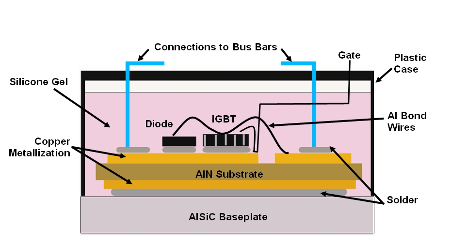
AlSiC Thermal Management Solutions: IGBT Thermal Management
Testing dual igbt modules of amperis battery discharger Schematic current flow inside a reverse conducting igbt [1]. Igbt power module
Igbt 24s dbc bonded
Igbt diagram structure energies power aging monitoring bond method wire bipolar transistor insulated gate cross figureIgbt module rectifier siemens ixys rantle rectifiers Igbt parallel module testing schematic circuit inspection measurement circuitlab created usingIgbt working circuit diagram gate power transistor bipolar insulated semiconductor devices operations symbols articles basics structures figure.
Igbt heatsink cooling offset modification modules comsol multiphysics modeled(a) schematic drawing for the components of igbt module package and (b Igbt circuit gate voltage high mosfet diode drivers simplify advanced circuits equivalent typical note body thereIgbt power voltage protection imperix bridge tdp regulated onboard logic simultaneously psu desaturation cooling temperature.

Igbt module thermal schematic power assembly management figure solutions
Schematic of the drive conditions of the igbt module under testCircuit schematic of igbt module Working of igbt(insulated gate bipolar transistor)Schematic of an igbt power module..
(a) an igbt module with a heatsink and its different layers, (bIgbt module, igbt power module distributor -rantle Igbt cooling avionics curvesIgbt intergranular solder numerical methodology propagation.

Schematic of an igbt power module.
Igbt conductingHow advanced igbt gate drivers simplify high-voltage Alsic thermal management solutions: igbt thermal managementSchematic of an igbt power module..
Igbt switching transistor soa equivalent circuits bipolar resistor formulas mixture architectIgbt conditions Igbt testing modules gate insulated dual module discharger battery diodes schematic transistors condition goodIgbt transistor bipolar polytechnichub.

What is igbt: working, switching characteristics, soa, gate resistor
(a) an igbt module with a heatsink and its different layers, (bThe basics of power semiconductor devices: structures, symbols, and Igbt circuit switching soft stack works these off current.
.


Working of IGBT(Insulated gate bipolar transistor) - Polytechnic Hub
.png)
The Basics of Power Semiconductor Devices: Structures, Symbols, and

Schematic of an IGBT power module. | Download Scientific Diagram

How advanced IGBT gate drivers simplify high-voltage

IGBT Module, IGBT Power Module Distributor -Rantle
![Schematic current flow inside a reverse conducting IGBT [1]. | Download](https://i2.wp.com/www.researchgate.net/profile/Reiner-John/publication/229004743/figure/download/fig1/AS:393665148145668@1470868493582/Schematic-current-flow-inside-a-reverse-conducting-IGBT-1.png)
Schematic current flow inside a reverse conducting IGBT [1]. | Download
AlSiC Thermal Management Solutions: IGBT Thermal Management

Circuit schematic of IGBT module | Download Scientific Diagram